Our civilization did not build Titanic, Olympic or Britannic. Theirs did. Was it the Tartarian one?

Once again, tackling a well known topic, I risk to sound ridiculous but hold your judgement till you have some material objections to make. Jumping ahead I will say, that the issue of "we did not build this ship" extends way beyond these three ships. In reality, this is one of those instances, where I would like this community to find a conventional explanation for the question I will pose. In other words, I would love to be proved wrong on this one, for we have videos, photos, blueprints, and what not.

The question I will pose is this - what did they use to connect 2.5 ton hull plates to each other? Rivets, invisible rivets, welding or glue?

superglue_1.png

There was a lot published about RMS Titanic and its two sisters, RMS Olympic and HMHS Britannic. For those who do not know, or their knowledge is superficial, below is a little recap.

All_three_Olympic-class_ocean_liners.jpg

The White Star Line faced an increasing challenge from its main rivals Cunard, which had recently launched the Lusitania and the Mauretania - the fastest passenger ships then in service - and the German lines Hamburg America and Norddeutscher Lloyd. The company sought an upgrade in their fleet primarily in response to the Cunard giants but also to replace their oldest pair of passenger ships still in service, being the SS Teutonic of 1889 and SS Majestic of 1890. All three Olympic-class liners were built by Harland and Wolff (Belfast). The plan to build these three ships was realized by naval architects Thomas Andrews and Alexander Carlisle.

Thomas_Andrews_AlexanderCarlisle_titanic.jpg

Alexander Carlisle got off the project in 1910 due to health problems. Thomas Andrews died on Titanic when she hit an iceberg on 14 April 1912. His body was never recovered.

RMS Olympic
RMS_Olympic_1.jpg

Although Olympic and Titanic were nearly identical, and were based on the same core design, a few alterations were made to Titanic (and later on Britannic) based on experience gained from Olympic's first year in service. The most noticeable of these was that the forward half of Titanic's A Deck promenade was enclosed by a steel screen with sliding windows, to provide additional shelter, whereas Olympic's promenade deck remained open along its whole length. This was a major contributor to Titanic's increased gross tonnage of 46,328 tons over Olympic's 45,324 tons, which allowed Titanic to claim the title of largest ship in the world.
  • Laid down: 16 December 1908
  • Launched: 20 October 1910
  • Completed: 31 May 1911
  • In Service: 1911
  • Out of Service: 1935
  • Hull plates held by: 3,000,000+ rivets
  • Fate: Retired at Southampton after 24 years service & scrapped. Superstructure dismantled at Jarrow, England, and the hull at Inverkeithing, Scotland.
  • Wiki link
RMS Titanic
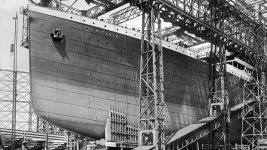
RMS_Titanic_1.jpg

Titanic was 882 feet 9 inches (269.06 m) long with a maximum breadth of 92 feet 6 inches (28.19 m). Her total height, measured from the base of the keel to the top of the bridge, was 104 feet (32 m). She measured 46,328 gross register tons and with a draught of 34 feet 7 inches (10.54 m), she displaced 52,310 tons.
  • Laid down: 31 March 1909
  • Launched: 31 May 1911
  • Completed: 2 April 1912
  • In Service: 10 April 1912
  • Out of Service: 15 April 1912
  • 2,000 Hull plates held by: 3,000,000+ rivets
  • Fate: Hit an iceberg 11:40 p.m. (ship's time) 14 April 1912 on her maiden voyage and sank 2 h 40 min later on 15 April 1912.
  • Wiki link
The 2,000 hull plates were single pieces of rolled steel plate, mostly up to 6 feet (1.8 m) wide and 30 feet (9.1 m) long and weighing between 2.5 and 3 tons. Commercial oxy-fuel and electric arc welding methods, ubiquitous in fabrication today, were still in their infancy; like most other iron and steel structures of the era, the hull was held together with over three million iron and steel rivets, which by themselves weighed over 1,200 tons. They were fitted using hydraulic machines or were hammered in by hand.
In other words, they did not use welding to put hulls together back in 1912 (or 1913, 14, 15, or 16).

HMHS Britannic
HMHS-Britannic_1.jpg

The dimensions of Britannic were similar to those of her sister ships, but her dimensions were altered whilst still on the building stocks after the Titanic disaster. With a gross tonnage of 48,158, she surpassed her sisters in terms of size (volume), but that did not make her the largest passenger ship in service at that time; the German SS Vaterland was significantly bigger.
  • Laid down: 30 November 1911
  • Launched: 26 February 1914
  • Completed: 12 December 1915
  • In Service: 23 December 1915
  • Out of Service: 21 November 1916
  • Fate: Sank after an explosion on 21 November 1916 near Kea in the Aegean Sea
  • Wiki link
For our little investigation we will need one additional ship. We will use USS Northland.

USS Northland
Northland_1.jpg

USS Northland was a cruising class of gunboat especially designed for Arctic operations that served in World War II and later served in the Israeli Navy. She was the last cruising cutter built for the Coast Guard equipped with a sailing rig.
  • Laid down: 26 August 1926
  • Launched: 5 February 1927
  • Commissioned: 7 May 1927
  • Out of Service: 1938–1939
  • Fate: Sold 3 January 1947
  • Wiki link
She was structurally reinforced to withstand hull pressures of 100 psi and lined with cork for warmth. One feature used in the construction was the welding of the hull rather than riveting; this was done for strength and was not a common practice in 1926.
Essentially, USS Northland was one of the first officially welded ships. You are welcome to find an earlier one, and I will gladly update this post with your finding.
To speed up and improve production, shipyards started using templates to manufacture prefabricated ships and replacing riveting with welding. The 2,710 cargo ships they built between 1941 and 1945 were called “Liberty Ships.” They were credited with helping to win the war.

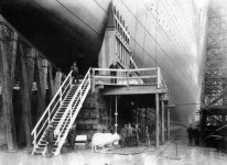
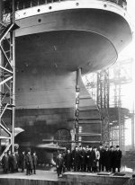
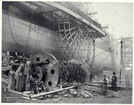
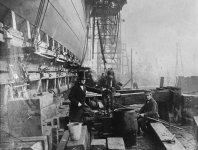
Construction of Titanic
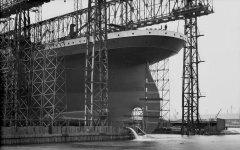
RSM Titanic is obviously the most publicized ship out of the three. Apart from its ill fate and the beautiful name, it is open for speculation why the most videos and photos pertain to Titanic, and not Olympic, for the latter was the first one to get launched. One way or the other, we have plenty of photos and YouTube videos of Titanic being built... or do we?

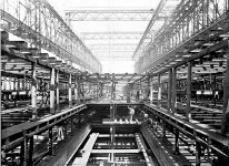
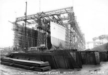
In reality, we only have a few stages of the construction of RMS Titanic. They are:
  • Keel Laying
keel_laying_titanic.jpg
  • Construction of the Frames
construction_of_frames_titanic.jpg
  • Construction of the Hull
You are welcome to look for those stages yourself, or here is a set of Titanic Construction Links for your convenience.
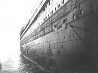
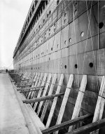
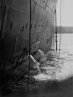
Where are the Rivets?
Images Source
Titanic_rivets_no_rivets_2.jpg Titanic_rivets_no_rivets.jpg Titanic_last_anchor_rasing.jpg

Rivets are very much visible, and distinguishable.
Titanic_rivets_no_rivets_1.jpg


Titanic Hull Rivets
The 401 Rivet is 3 3/4″ long, with a shank diameter of 1″ and head diameter of 1 3/4″. Each one weighs just over 1 pound.
Titanic. Ship Number. 401. Vessel Type. Passenger Ship. Built. Belfast. Yard. North Yard.

Titanic_hull_rivet.jpg

Titanic_rivets.JPG

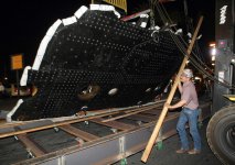
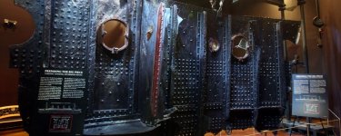
Rivets dot the surface of the "Big Piece," the largest recovered section of the Titanic's hull. The 15-ton section of the doomed luxury liner is part of a touring display of more than 300 relics from the ship called "Titanic"

rms_titanic_the_big_piece.jpg

titanic-big-piece.jpg titanic-artifact-exhibition-big-piece.jpg
With all the video, and photographic evidence we have where is the Titanic, or Olympic or Britannic at the stage where their hulls are 1/8, 1/4, 1/2 complete? How did they attach those bottom 2.5-3 tons, 6 foot by 300 foot still plates? Did they weld them together, or did they glue them together? And why did they have to use rivets above the unriveted portion?

Flush Rivets
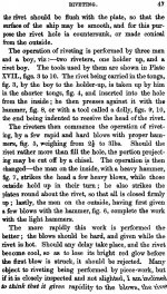
There is an interesting couple of paragraphs in the 1868 book titled "Iron Ship-building, with Practical Illustrations". It could almost solve the mystery if it was not for the lack of evidence of such an "invisible" flush rivet. If you can find what this particular rivet looks like, please post a link, or upload a picture. Also, if you can find any mentioning of the flush rivets in the Titanic's, or any other ships construction, please share your finding. For right now, the only official rivets are the ones displayed above. Below you can see two pages covering these "flush rivets".

flush_rivet_1.jpg flush_rivet_2.jpg

After all, how invisible can iron rivets be?

Titanic...
Titanic_last_anchor_rasing-2.jpg


Where are the rivets on Olympic?
Source
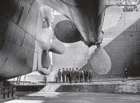
Olympic propeller shot. This is a huge image you can zoom in on. You will find a few rivets in there, closer to the rudder. The remainder is mystery.

Olympic's_propellers.jpg

Where are the rivets on Britannic?
Source

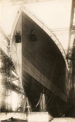
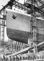
Britannic_hull.jpg Britannic_hull_1.jpg Britannic_hull_3.jpg Britannic_hull_4.jpg

It gets better. Where are the rivets on this 1856 ship:

1856 SS Great Eastern a.k.a. Leviathan
Source
Great_Eastern_Leviathan_hull.jpg

Great_Eastern_Leviathan_5.jpg Great_Eastern_Leviathan_15.jpg

Evidentiary King - USS New Hampshire - 1906
Here is a 28.6 MB TIFF image link to a huge image of this ship. If you can find a rivet here, I would like to hear about it. What you will find there is a few of the seams looking just like welding seams look.

USS_New_Hampshire_c1910.jpg


Finding close enough images of those early 20th century "high-tech marvels of their time" is hard. But they are out there, and sometimes they pose questions. There are multiple videos out there which show ships being built, like this one of supposedly RMS Olympic... or it could be 1930 RMS Queen Mary, or any other ship for that matter. Those videos show something and nothing.

Weird Stuff
We do have a few contradicting images showing both, rivets and no rivets like these two images of the RMS Olympic propeller area. One clearly shows the lack of the rivets, the other one shows rivets present. What can this inconsistency tell us? The rivets on the first image are visible from 10 miles away. The second image has a few rivets closer to the rudder, but no other ones are visible.

Olympic-Propeller.jpg Olympic's_propellers.jpg

I present a simple question, if rivets were not used, and welding was not available around 1912 (definitely was not in 1856 for SS Great Eastern), how were those plates attached to each other in the unriveted areas? Superglue was invented in 1942, so they could not use that.

In Reference to the Rivet Visibility - they are visible
rivets_visible.jpg

rivets_visible_1.JPG rivets_visible_3.jpg

Propeller Story
Additionally, you will not find a name attached to the invention of a VPP (variable pitch propeller). General Wiki link on propellers is here. All three of our Olympic-class ships had 2 Variable pitch propellers, and 1 Fixed Pitch Propeller. I talked about the difference between the VPP and FPP in the article about SS Great Eastern. In a nutshell the below two images show the difference between VPP and FPP.
  • Variable Pitch Propeller - the blades rotate via a complex mechanism inside the hub.
variable-pitch.jpg
  • Fixed Pitch Propeller - the blades are permanently attached (welded if you will) to the hub.
Voroshilov_cruiser_propeller_at_the_Museum_on_Sapun_Mountain.jpg

Now think about it.
  • Telegraph inventor: Samuel Morse
  • Radio inventor: Guglielmo Marconi (Popov if you want)
  • Telephone inventor: Bell and Meucci
  • Light Bulb inventor: Edison
  • This, and that, and all of the above inventor: Tesla
  • Variable Pitch Propeller inventor: WHO?

Interiors
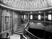
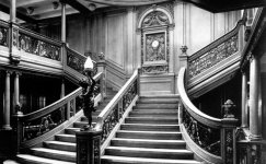
Interiors were worthy of the "Tartarian" architecture (for those who knows of what I am talking about).


KD Hypothesis: Starting with the mid-19th Century, and ending with approximately 1917-1920s, Britain, and Germany (possibly USA, and France as well) acquired (through military involvement) a number of the Tartarian Ships of superior quality. The Grand Tartary was obviously destroyed, and wiped out from history. Not being able to use the ships the way they were (military induced damage, or technological mismatch - Titanic's electrical plant was capable of producing more power than an average city power station of the time), the victors (or the survivors, or vultures) had to repair, refurbish, and adjust them to their technological level (coal fuel, etc). For that purpose dry docks were constructed. Captured ships were adjusted in those docks. Ships originally had no funnels, due to different "cleaner" fuel used to power their steam engines. Funnels were installed to accommodate hundreds of tons of ash emitted by the readjusted engines.

the-building-of-titanic.jpg

Poor understanding of the acquired machinery meant multiple operational errors, and consequent short life span of these ships. That is unless ship welding was available in 1856, and 1912. Otherwise what did they use to hold those plates together - invisible rivets? Super strong glue could also be an option, I guess.

That is unless ship welding was available in 1856, and 1912. Otherwise what did they use to hold those plates together - invisible rivets? Super strong glue could also be an option, I guess.
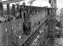
 
Although it is quite clear that these boats were part of the package inherited from the previous humanity, I wonder why they used steam rather than electric engines on them.
 
Although it is quite clear that these boats were part of the package inherited from the previous humanity, I wonder why they used steam rather than electric engines on them.
How is it quite clear?
 
One thing I can’t reconcile is the abutment of the panels. Some ships demonstrate obvious vertical and or horizontal lapping of the panels, while others appear flush. Whether the panels are lapped or not doesnt appear to follow whether they’re riveted or welded.

I also am reminded of the “artisan” argument… with “less tech” how were they able to achieve such extravagant, detailed, precise, and refined design? Designs which at this scale, aren’t feasible nor economical enough for practice.
 
Last edited:
There was no welding. All plating is riveted to frames and each other.
de02bt.jpg

I first posted that here in April 2021.
In this one the Olympics propellers are being fitted and the hull is being painted with the afore mentioned shiny enamel stuff.

And this one showing frames and rivets.
titanics-steel-hull-framing-1911.jpg

Olympic this time. Rivets and rivet holes clearly visible.

tumblr_maosbu4qee1qmyxbjo7_500.jpg
 
Last edited:
but where are the rivets? Why can you see them up high but not down low?
 
but where are the rivets? Why can you see them up high but not down low?
The rows of holes in the frames and plates around the exposed propeller shaft are where the rivets were. They have been removed to repair the plating that was damaged in the collision with the Royal Navy cruiser.

IMG_20220913_062212.JPG

The undamaged plates are covered in the composition called Rahtnjen's and as the plating below the waterline uses flush rivets this is why they seem to disappear. Go to the linked thread in the archive and have a read.

Below the water-line more than usual care has been taken to diminish skin friction as much as possible, and to accomplish this the plating has been carefully cleaned, rubbed down and smoothed, then treated with a coating of Rahtnjen's celebrated composition. So nicely has this been done that the bottom plating of the Teutonic is as smooth as glass, having the appearance of an enameling process.


Here is another photo from that thread of Olympic in drydock and due to the lighting the rivets and their patterning are clearly visible.

IMG_20220913_063847.JPG

Edit to add
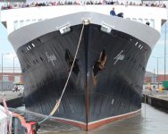
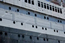
I looked for a comparative photo of the QE2 but this time its her bow not stern. Reason for choosing QE2 is she was the last purpose built ocean liner. Her hull is of all welded construction and in comparison to Olympics diverted hull is very smooth and regular.
I have included a photo of QE2's stern in drydock after fifty years at sea and as blurry as it is to illustrate the different appearance of welded plating to riveted.
download-11.jpeg

download-10.jpeg

Again from the linked thread the sepia photo i posted earlier shows the underwater plating in the process of having the coating, quoted above, applied.
de02bt.jpg
 
Last edited:
Alright, I hear that, but a flush rivet isn’t an invisible rivet.

looking at this photo:

1663125144916.jpeg

the boat is in the water, so it’s safe to assume the hull is completed. The surface mounted rivets are clearly visible, but not so much as a trace of any rivets down low, flush or otherwise.

the pictures that you’ve offered clearly illustrate surface rivets on the lower portion of the hull, but this photo clearly shows none.

I’m not firmly planted on either side of the issue, but I feel like this is far from settled.

EDIT/ADDENDUM:

if this process of “smoothing” and “coating” was performed… it sounds like a truly labor intensive feat. Why would they bother doing so up to 20’ above the water line?

with a “flush rivet” something would still have to protrude above the surface to grip the plates. A coating of whatever, liberal enough to flatten out any rivet heads, I would imagine it would also be enough to smooth the lapping on the panels. I imagine wrong? If they were that concerned with surface friction, I would think they would focus on the squared off edges of the panels rather than the rounded rivets.

lastly, saying “flush rivets” unequivocally while there is next to zero reference, evidence, or history of them feels like a narrative cop out. Especially when “flush rivet” looks like this in literature:
1663209962832.jpg

also, as flimsy of a citation as Wikipedia is, it says this:

“Flush riveting was invented in America in the 1930s by Vladimir Pavlecka and his team at Douglas Aircraft.”

it seems to be focused on aircraft for flush rivets, but I would imagine that an undertaking as large as the titanic would be worth mentioning
 
Last edited:
You wouldn't know this but I have worked on a vessel built in 1919 which was all riveted construction. It was an Admiralty floating dock. This dock was not powered and went up and down in the dock it was floating in.
The plating on the hull was raised head rivetting. The plating on the deck where the ship was lifted and worked on had flush head rivetting.
Of course no way for me to prove this too you in any way.

I also worked on another Admiralty floating dock built in 1959. This one was all welded construction. The difference in the hulls of the vessels is so marked it cannot be missed. The most obvious is the smooth plating on the 1919 docks hull and the distorted plating on the all welded hull of the 1959 dock. This difference is caused by the heat of the welding. It buckles the plate enough to be noticeable and is still visible on ships built today in fact more noticeable as the hull plating is thinner today than even 1959.

I didn't say the coating made raised head rivets disappear. If you ever come across a rivetted ship in the flesh you would see how absurd the idea is.

The Olympic class ships were built for speed. The biggest drag on the ship is the water. The smoother the underwater hull the faster it goes in contrast to a hull made with raised head rivets when flush rivets are used.
The coating decreased the drag just as the flush rivets did.

The alamy image showing the coating being applied shows in crystal clarity the difference between uncoated plating and coated. How far up the hull the coating went is something I don't know. But in your photo the only part of the hull with raised head rivetting is the banding where hull meets superstructure. Above that banding the rivetting reverts to flush rivering. Again I know not why but external appearance could be the reason.

It makes zero sense if welding of plates to frames had been developed at the time the Olympic class ships or their predecessors, Teutonic, Oceanic etc (for they also had smooth below waterline plating and the coating) rivetting would feature anywhere in the hull construction process.

But despite appearances I am not attempting to convince you or anyone else into believing me. I am simply relating what I see and what I know from experience.

These vessels, the ocean speedsters of their day, were not found sat on the stocks somewhere or floating in a port awaiting discovery. Powering through the ocean kills all ships sooner or later. The sea attacks the fabric of the vessel and its raw power weakens metal to the point it fails often catastrophically but equally just enough to render the hull unseaworthy. Such hulls are taken out of service and scrapped or sunk or on rare occasions laid up as floating museums. Crucially they are never put back into their intended service function. This is simply because they are no longer seaworthy.

Smaller vessels are sometimes restored to working order, see the SS Waverley for one example but the amount of maintenance and ongoing repair they need is challenging to say the least.

For me until anything else comes to light I haven't yet found my take is this.
Titanic did not exist.
The Olympic class was a two ship class Olympic, the lead ship and Brittanic.
Most of the photographs labelled Titanic are likely of Olympic.
It makes zero senser for there to be fewer named photographs and articles for the lead ship than the second ship buily., zero sense.
Why the scam of Titanic was run I have no idea and frankly I have next to no interest in trying to work out as I don't feel it is possible at this distance in time.

It is possible the ship sailing under thed name Titanic was neither the Olympic or Brittanic but was a modified or altered foreign built hull made to look like an Olympic class ship. There's were a lot of very similar sized three and four stacker liners about in the world at that time.
One avenue I have considered but not explored is looking for evidence of crew make ups in terms of nationality, rotations, specifically the officer portion as there are fewer of them of a higher social class so likely more has been written about them and possibly more photographs digitised.

The idea the Olympic class belonged to an earlier civilisation that vanished almost instantaneously to leave working or useable artifacts behind for a new civilisation to take over, figure out how to operate, repair and put these ships to use on the transatlantic crossing is absurd as the predecessor classes of liner show a clear progression in speed and scale going back into the 1800's a progression that continued after the Olympic class through to the time I was born

Edit.
Ngram is as unreliable as wikipedia in my book. Both are way to easy to manipulate.


Here is a primer on rivetting that has a bearing on when they entered widespread use.
This article is even better. I have witnessed the process described in this quote.
The hot rivets are handled with long tongs that are regularly cooled in water. The diameter of the rivet shank is a little less than the hole diameter, i.e. 3/4” rivet is used for a 13/16” hole. The shank length needs to have enough material to fill the hole and to form the head when compressed. The “rule of thumb” for the shank length of a 3/4” rivet is the combined plate thickness to be joined plus about 1”. Extra length may be needed for the head or countersink. If the holes do not perfectly line up, then a little extra length may be required after reaming. Always do a dummy run to get it right for a certain combination.

Again you won't know and I cannot find a picture of the tools to show you but basically the tool used to shape the head of the red hot rivet is itself shaped to produce the desired result. They are hammered from both sides at the same time to create the watertight seal.
Some produce domes, some flat. In the case of flush riveting the plate is countersunk and the rivet is shaped by the tool to fill the countersink on the seaward side and domed on the shipboard side.
 
Last edited:
I appreciate and do not wholly discount your historical experience. The explanation provided is feasible in and of itself.

There are simply some inconsistencies for me:

the image of them “applying the coating” shows them applying it to an already rivetless surface. Where are the pictures of them applying the first coating?

if they were so greatly concerned with the hydrodynamics of the hull that it warranted flush rivets and machining/coating… why are there such unruly laps? I’m no engineer, but I would imagine that those right angular lapped panels would have more pronounced effects on dynamics than rounded head rivets.

Again, I’m not saying that the narrative is or isn’t correct, or that KD’s supposition is or isn’t correct.

it’s entirely possible that I simply cannot comprehend the how/why of the construction techniques. It’s entirely possible that the hull and the superstructure were built by different civilizations. I fantasize about some sort of cold-welding chemical process that we no longer know.

in consideration of the apparently inherited trains and trolleys, why couldn’t we have inherited ships too?
 
As I explained. The hull plates rivets were knocked down into a precut countersink that is why they appear to disappear until the lighting of a photograph reveals their presence even under the coating.
The coating is likely to be a single coat coating.

As for any transportation device somehow surviving long enough for a replacement civilisation to arrive from lands beyond the known or wherever, figuring out what they have found, learn how to fix 'em up after learning how they work of course, re discovering and opening the mines, the smelters, the infrastructure around such facilities, then putting them to their intended use surely takes considerable time.

That is assuming the new civilisation was a dumb one.

Assuming it wasn't dumb then chances favour it having its own technologies, processes, methods, experience to hand and would carry on with those I would of though just ignoring the pre existing or scrapping it all to use its components unless they reckoned them superior to their own and set too to work out how they worked and got them going again.

Assuming it was a much more technologically advanced new civilisation it would have no need of antiques so best they would do is perhaps harvest materials or clear them away.

No matter how its cut the arguments for transpotation objects lasting in usable fettle long enough for a new civilisation to put to use the logistics of such an idea don't fly for me, as you may have guessed.

That we are ignorant of what really went on is no great surprise once you accept those telling us they really know what went are making shit up to hide the fact they are as clueless as us. Difference being we here have bugger all to lose the liars in academic and governance circles have everything to lose.
 
You have a viable explanation for the how. It’s possible that these photos all have the elusive flush rivets hiding in the shadows and we just can’t see them. For argument’s sake let’s accept that.

why?

why go far higher than the water line will ever be? What’s the justification for the labor and investment?

why were the engineers so devoted to smoothing out these rivet heads in the name of dynamics/drag, but so oblivious to the effects of squared off panel laps?

people seem to (at least, with regard to educated folk like engineers) do things that make sense. This doesn’t make sense. I’m sure these boats had a budget, and that these boats had design specifications. The supposition that there are flush rivets hidden beneath some fancy coating stands all by itself, but seems diminished by the other factors including the height of the flush work, and the disregard of the panel lapping.

They could have abutted the panels against eachother and riveted them flushly to plates behind them, similarly to how the superstructure is done. But they didn’t, they overlapped the panels.
 
why go far higher than the water line will ever be? What’s the justification for the labor and investment?
I don't know and wouldn't know where to look. Presumably plans might exist somewhere but they haven't been digitised.
My guess is as I said aesthetics. It takes the same length of time, the same amount of effort, the same material, the same process to put every shape of hot rivet and secure the joint.
So it matters not from the time angle which rivet goes where
The plating in this part of the hull is level though the overlap the thing that imparts strength to the whole hull is still visible but its done in straight rows.
Hence my guess at aesthetics.


why were the engineers so devoted to smoothing out these rivet heads in the name of dynamics/drag, but so oblivious to the effects of squared off panel laps

Small raised parts of hulls create exponentially more drag than large raised parts. For example the prop shaft bulge being repaired in the alamy photo is designed, shaped constructed for minimum drag. If the rivets used were dome headed rivets the drag of the rows of individual domes would reduce speed and may increase vibration in that part of the hull.
Then their is cavitations to consider. A flush head rivet knocked into a countersunk hole stops the drag and the cavitations from being a problem.
There is a trade off with the lapped joints of the plate producing edges which themselves cause drag and cavitations however the need for underwater strength to ensure as long and profitable life as possible for the hull is a primary concern for the designers.
The lapping of underwater plating is much stronger than the lapping above water.

The amount of stress the underwater hull gets from being forced through water by any form of power is what determines the life of the hull. The stronger the underwater hull the longer it remains safe to operate. The longer its operators can make a profit from the hull.

You cannot tell in any of the photographs where the underwater coating ends and the hull painting begins. Based on experience the change over is usually at the waterline as can be clearly seen in the QE2 photo. The red portion of her hull is always underwater when fully stored and fully ballasted.
 
You guys have a wonderful debate :) here is a good quality close-up image.

titanic-11.jpg
 
I don’t know enough about engineering and aero/hydro dynamics to mathenarucalyargue (mathematically argue lol) your point:

“Small raised parts of hulls create exponentially more drag than large raised parts”

but I can say, my gut disagrees with that statement. What I do know tells me this: a rounded feature, while inducing drag, directs the medium (air or water) around/over the obstruction. A perpendicular feature doesn’t direct the medium over/around, but rather against and opposite the surface.
evidenced by long haul truckers with cowlings like this:

1663433094929.jpeg

instead of allowing the large flat trailer face to create drag like this:

1663433139833.jpeg

I don’t have access to catalogs and manufacturing costs from the time, but I’m also going to make a few assumptions and inferences:

flush rivets require countersunk rivet holes. Drilling these holes requires more complex equipment, more expertly skilled technicians, ergo greater cost. The cost of the rivets themselves may be comparable, though in my experience, better designed hardware costs more whether or not the materials do.

in all of the reading that I’ve done on flush rivets and their boat coatings, since we’re quoting anecdotal knowledge, I’ve learned that after securing the rivets they’re often machined smooth to get the full effect of flushness. This machining also requires tools and labor.

assuming those two thoughts to be true, doing flush rivets 20’ higher than necessary doesnt pencil out. 20’ multiplied by the perimeter of the hull is a lot of square feet to cover.

From an aesthetics standpoint, wouldn’t they be more concerned with the superstructure? The part that everybody sees?

mowing my lawn in a cross hash pattern looks better than alternating strips aesthetically. However, if I did the front half of my lawn in cross hash, and the rear half of my front lawn in alternating strips… the lack of uniformity has a greater impact on aesthetics than the choice between hash and strip.

again, I believe the productive component of humanity does things as efficiently and sensibly as possible.

another non-corroborating factor is the photo of the prop with a large, riveted patch or brace above it. If those rivets are so lacking in dynamics, why would they be used right next to the propeller where the water is moving fastest?
 
Last edited:
In 1942 Walt Disney made this film for Lockheed & the National Film Board of Canada.


Do we have any evidence of this technology being used while building the ships in question?
 
In honor of Occam’s razor, I’d like to explore the assumptions involved in both scenarios:

flush rivets:
  • They were available at the time
  • In their infancy, they were able to be 100% obfuscated by a coating
  • The dynamic drag of rivet heads was of dire importance, however the uneven panel lapping was of no importance
  • The additional/unnecessary surfaces that were flush riveted bore either no economic hardship or justifiable economic hardship
  • The additional/unnecessary surfaces that were flush riveted were done so for aesthetic purposes
Not flush rivets:

since I took the liberty of itemizing your assumptions, I’ll ask you to itemize mine
 
Here is the hull of Olympic after her launch when she was drydocked to remove the launch cradle. In it the flush riveting I am banging on about is clear as day. Perhaps I was wrong about the coating and its a multi layer coating but its not been applied in this photo. The launch cradles have domed rivets.
The cradles are fixed by rivet through the hull plate directly to the hull frames.
How they remove them is by burning through the rivet head or drilling kit out. Then a brand new hot rivet is used to once again fully seal the plating.

mev-11091429.jpg

As you can see the launch cradles themselves are of riverted construction.
Using a truck which travels through air as an example of the impact of drag in water is true apples to oranges.

No point me going over the same ground again and again. Obviously I am crap at explaining. You see some other method of construction being used based on the photographs you see.
Either some form of welding or some form of unknown construction. I know RMS Olympic had a fully rivetted hull from the lack of distortion to the individual plates. There are two photographs of the rivets in the underwater plating quite clearly visible in drydock.

I don't feel there is anything more to add.
There used to be and still might be a Pathe newsreel on a website, may even be on YouTube showing how the rivetting process was done during WW2. Might be worth tracking down.

Edit to fix inevitable missed autocorrect daftness.
Second edit to add this photo of Olympic.

mev-11091428.jpg

 
Last edited:
Air and water are incredibly similar in terms of dynamics. Obviously drag in water is far greater than air, but my hand held flat and perpendicular to motion through the air creates more drag in both air and water, opposed to my hand open and facing down, which slices through air and water much easier.

1663436292711.jpeg

this illustration challenges your statement about rivets creating more drag than flat angular laps.

Fluid Dynamics: “In physics and engineering, fluid dynamics is a subdiscipline of fluid mechanics that describes the flow of fluids—liquids and gases. It has several subdisciplines, including aerodynamics (the study of air and other gases in motion) and hydrodynamics (the study of liquids in motion).”

Air is a fluid: “In physics, a fluid is a liquid, gas, or other material that continuously deforms ( flows) under an applied shear stress, or external force.”

Addendum: still I cannot say whether I sit on a particular side of this fence, but here’s some more info of interest:
  • cannot find any mid-way progress pictures. Either so little work has been done that it could be nothing/anything, or it jumps to the entire hull is complete
  • This picture of the hull of the Olympic:
1663472502366.jpeg


those certainly do not look flush to me.
 
Last edited:
You should post sources of photographs and or quotes It helps people landing on this thread.
But I'm out. I've been talking shite.
 

Similar articles

Back
Top